World of Level Design™
Tutorials to Becoming the Best Level Designer and Game Environment Artist (since 2008)
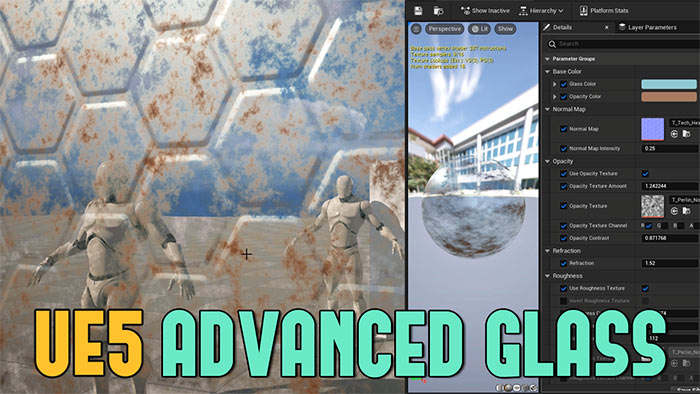
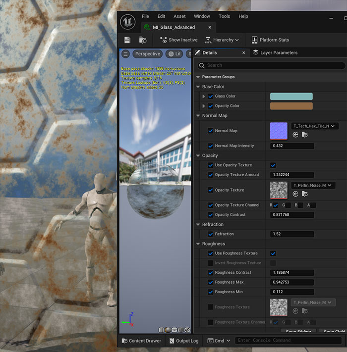
In this comprehensive tutorial, I'll guide you through creating an advanced glass material in Unreal Engine 5 (UE5) with extensive controls for opacity, roughness, normal maps, and base color.
Unlike the basic glass material covered in a previous tutorial, this advanced version offers greater flexibility, allowing you to customize glass appearance with textures, adjust distortion with refraction and introduce secondary colors for a more realistic and dynamic look.
Let's dive into the process of setting up a fully customizable glass material that you can tweak to suit any environment.
Video Tutorial
Prerequisites
- Basic understanding of UE5's Material Editor.
- A scene with simple static meshes (e.g., a plane and a sphere from the Place Actors panel under Shapes) to test your glass material.
- Access to UE5's Starter Content for textures (or your own textures).
Step 1: Setting Up the Material
Create a New Material:
- Right-click in the Content Browser, select New Material, and name it M_Glass_Advanced or something similar.
- Double click on the material to open the Material Editor.
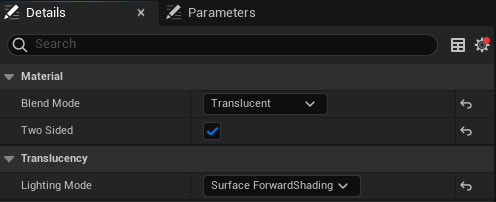
Configure Material Properties:
Select the main material node and adjust the following.
- Blend Mode: Set to Translucent.
- Lighting Model: Under Translucency, set to Surface Forward Shading for better visual quality (note: this is more performance-intensive than Surface Translucency Volume).
- Two-Sided: Enable this option for rendering on both sides of a mesh (e.g., for a single plane). This is optional and can be toggled later based on your needs.
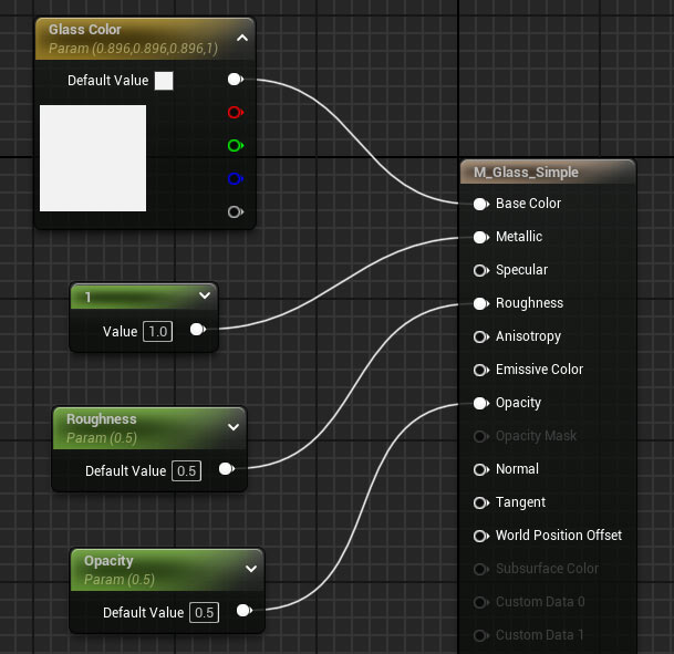
Initial Glass Setup
Opacity:
- Create a Scalar Parameter (hold S and left-click) named Opacity with a default value of 0.5.
- Connect it to the Opacity input of the material node.
- Assign it to a group named Opacity for better organization in the material instance.
Roughness:
- Create another Scalar Parameter named Roughness with a default value of 0.5.
- Connect it to the Roughness input to control how shiny or dull the glass appears.
- Assign it to a group named Roughness.
Base Color:
- Create a Constant 3 Vector (hold 3 and left-click), convert it to a parameter, and name it Glass Color.
- Set a default color (e.g., a slight blue) and connect the RGB output to the Base Color input.
- Assign it to a group named Base Color.
Metallic:
- Create a Constant 1 Vector (hold 1 and left-click) with a value of 1.
- Connect it to the Metallic input. This ensures the material renders as glass rather than plastic.
Here is the full setup so far:
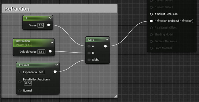
Refraction:
Enable refraction by setting the Refraction Method to Index of Refraction in the main material node.
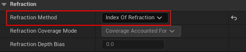
- Create a Fresnel node to control refraction based on viewing angles.
- Create a Scalar Parameter named Refraction with a default value of 1.52 (the physically accurate value for glass).
- Create a Constant 1 Vector with a value of 1.
- Use a Linear Interpolate (Lerp) node:Connect the Constant 1 Vector to Lerp A.
- Connect the Refraction parameter to Lerp B.
- Connect the Fresnel node to Alpha.
- Connect the Lerp output to the Refraction input of the material node.
- Assign the Refraction parameter to a group named Refraction.
- Select all refraction nodes, comment them (press C), and name the comment Refraction.
Test the Material:
- Create a Material Instance by right-clicking the material and selecting Create Material Instance. Name it MI_Glass_Advanced.
- Apply the material instance to the sphere and plane in your scene.
- Test the material by adjusting Opacity, Roughness, Glass Color, and Refraction in the material instance.
Step 2: Expanding Roughness Controls
To add variation to the glass surface, introduce a roughness texture with controls for channel selection, contrast, intensity and inversion.
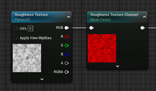
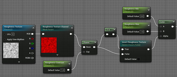
Add a Roughness Texture:
- Drag a texture (e.g., T_Noise from Starter Content) into the Material Editor.
- Convert it to a parameter named Roughness Texture and assign it to the Roughness group.
- Add a Component Mask node, convert it to a parameter named Roughness Texture Channel, and set the default to the Red channel.
- Connect the texture's RGB to the Component Mask input and the mask output to the Roughness input.
- Assign the Component Mask to the Roughness group.
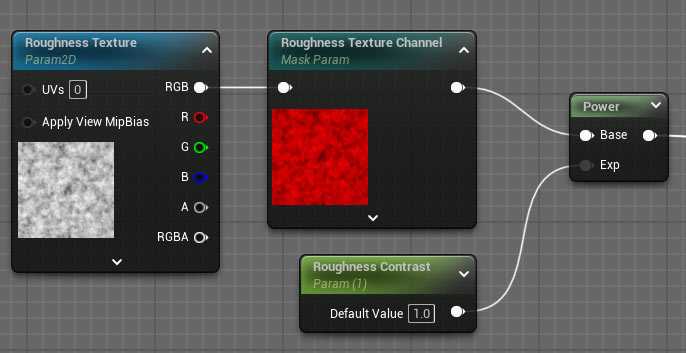
Adjust Contrast:
- Add a Power node to control contrast.
- Create a Scalar Parameter named Roughness Contrast with a default value of 1 (no change).
- Connect the Component Mask output to the Base input of the Power node and the Roughness Contrast parameter to the Exponent input.
- Connect the Power output to the Roughness input.
- Assign the Roughness Contrast parameter to the Roughness group.
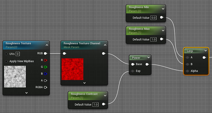
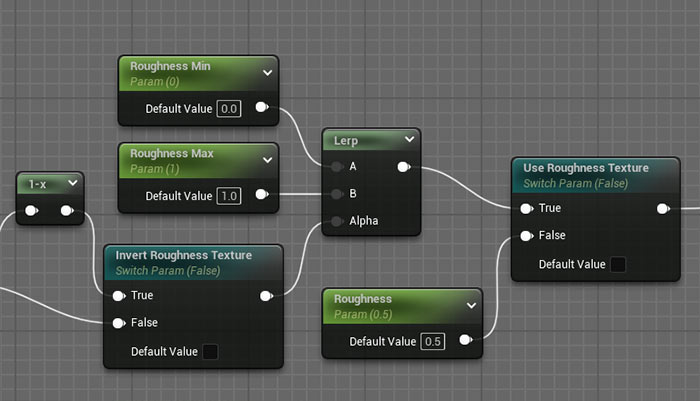
Control Intensity with Min/Max Values:
- Add a Linear Interpolate (Lerp) node.
- Create two Scalar Parameters: Roughness Min (default 0) and Roughness Max (default 1).
- Connect Roughness Min to Lerp A, Roughness Max to Lerp B, and the Power node output to Alpha.
- Connect the Lerp output to the Roughness input.
- Assign both parameters to the Roughness group.
Invert the Texture:
- Add a One Minus node to invert the texture's black and white values.
- Add a Static Switch Parameter named Invert Roughness Texture with a default value of False.
- Connect the Component Mask output to the One Minus input and the One Minus output to the True input of the Static Switch.
- Connect the Component Mask output directly to the False input of the Static Switch.
- Connect the Static Switch output to the Power node's Base input.
- Assign the Static Switch to the Roughness group.
Static Switch Toggle Roughness Texture:
- Add another Static Switch Parameter named Use Roughness Texture.
- Connect the original Roughness parameter to the False input and the Lerp output to the True input.
- Connect the Static Switch output to the Roughness material input..
- Assign it to the Roughness group.
- Select all roughness nodes, comment them (press C), and name the comment Roughness.
Test the Roughness Controls:
Toggle Use Roughness Texture to switch between a single roughness value and the texture-based setup. Adjust Roughness Texture Channel, Roughness Contrast, Roughness Min/Max and Invert Roughness Texture to see the effects.
Step 3: Expanding Normal Map Controls
Normal maps add surface detail and distortion to the glass, simulating designs or patterns.
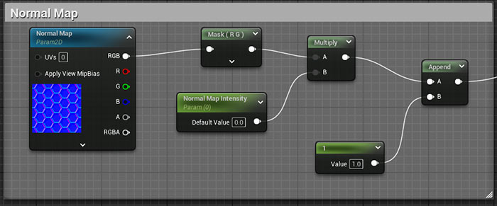
Add a Normal Map:
- Drag a normal map texture into the Material Editor.
- Convert it to a parameter named Normal Map and assign it to a group named Normal Map.
Control Normal Map Intensity:
- Add a Component Mask node, selecting only the Red and Green channels.
- Create a Scalar Parameter named Normal Map Intensity with a default value of 0 (flat normal).
- Add a Multiply node, connecting the Component Mask output to Multiply A and the Normal Map Intensity parameter to Multiply B.
- Add an Append Vector node. Connect the Multiply output to Append A and a Constant 1 Vector (value 1) to Append B to reintroduce the blue channel.
- Connect the Append output to the Normal input.
- Assign the Normal Map Intensity parameter to the Normal Map group.
- Select all normal map nodes, comment them (press C), and name the comment Normal Map.
Test the Normal Map:
Adjust Normal Map Intensity in the material instance (e.g., set to 1 for default, 0.25 for subtle effects, or higher for stronger distortion). Swap the Normal Map texture to test different patterns.
Step 4: Expanding Opacity Controls
To add variation to the glass's transparency, use an opacity texture with similar controls to the roughness setup.
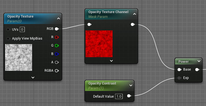
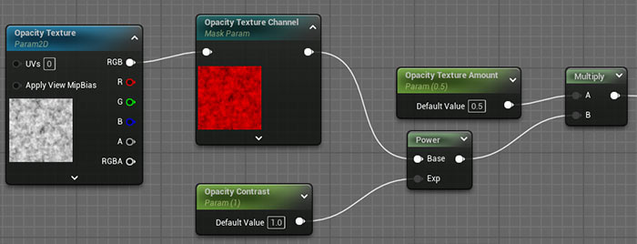
Add an Opacity Texture:
- Insert a black and white texture into the material editor, you can use the same texture you are using for roughness setup to get started
- Convert it to a parameter named Opacity Texture and assign it to the Opacity group.
- Add a Component Mask node, convert it to a parameter named Opacity Texture Channel, and set the default to the Red channel.
- Connect the texture's RGB to the Component Mask input and the mask output to the Opacity input.
- Add a Power node to control contrast.
- Create a Scalar Parameter named Opacity Contrast with a default value of 1 (no change).
- Connect the Component Mask output to the Base input of the Power node and the Opacity Contrast parameter to the Exponent input.
- Connect the Power output to the Opacity input of the material node.
- Assign all nodes to the Opacity group.
Combine with Global Opacity:
- Add a Multiply node.
- Create a Scalar Parameter named Opacity Texture Amount (default 0.5).
- Connect the Power output to Multiply B and the Opacity parameter to Multiply A.
- Connect the Multiply output to the Opacity input.
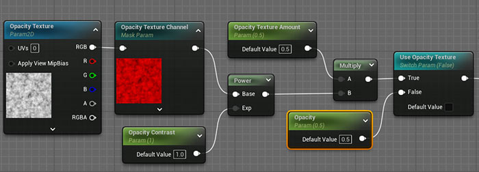
Static Switch Toggle Opacity Texture:
- Add a Static Switch Parameter named Use Opacity Texture with a default value of False.
- Connect the original Opacity parameter to the False input and the Multiply output to the True input.
- Connect the Static Switch output to the Opacity input.
- Select all opacity nodes, comment them (press C), and name the comment Opacity.
Test the Opacity Controls:
Test Opacity controls in the material instance by toggling Use Opacity Texture. Adjust Opacity Texture Amount, Opacity Contrast, and Opacity Texture Channel to control transparency variation. Swap the Opacity Texture to test different masks.
Step 5: Expanding Base Color Controls
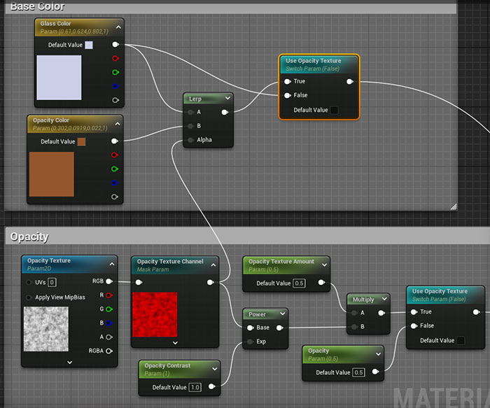
To enhance the glass's appearance, you can add a secondary color based on the opacity texture.
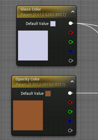
Add a Secondary Color:
- Create a Constant 3 Vector, convert it to a parameter named Opacity Color, and set a default color (e.g., a brownish tone for dirt).
- Assign it to the Base Color group.
Lerp Between Colors:
- Add a Linear Interpolate (Lerp) node.
- Connect Glass Color to Lerp A, Opacity Color to Lerp B, and the Opacity Texture Channel output (from the opacity setup) to Alpha.
- Duplicate the Use Opacity Texture static switch parameter (press Ctrl+D).
- Connect the Glass Color to the False input and the Lerp output to the True input.
- Connect the Static Switch output to the Base Color material input.
- Keep the duplicated switch in Opacity group.
- Select all base color nodes, comment them (press C), and name the comment Base Color.
Test the Base Color Controls:
Test the secondary base color through the material instance.
Enable the Opacity Texture Use switch then adjust Glass Color and Opacity Color to see the secondary color applied based on the opacity texture. Adjust Opacity Texture Amount and Opacity Contrast.
Final Testing
Apply the material instance to your scene's Static Meshes.
Experiment with all parameters:
- Opacity: Global transparency and texture-based variation.
- Roughness: Single value or texture-based with contrast, min/max, and inversion.
- Normal Map: Intensity and texture swapping for surface detail.
- Base Color: Glass color and secondary opacity-based color.
- Refraction: Distortion amount and angle-based effects.
Ensure all controls work as expected.
Save and Refine:
- Save the material and material instance.
- Test with different textures to customize the glass further.
- Adjust parameters to achieve the desired look, such as dusty, dirty or patterned glass.
Complete UE5 Material Graph Setup (Advanced Glass)
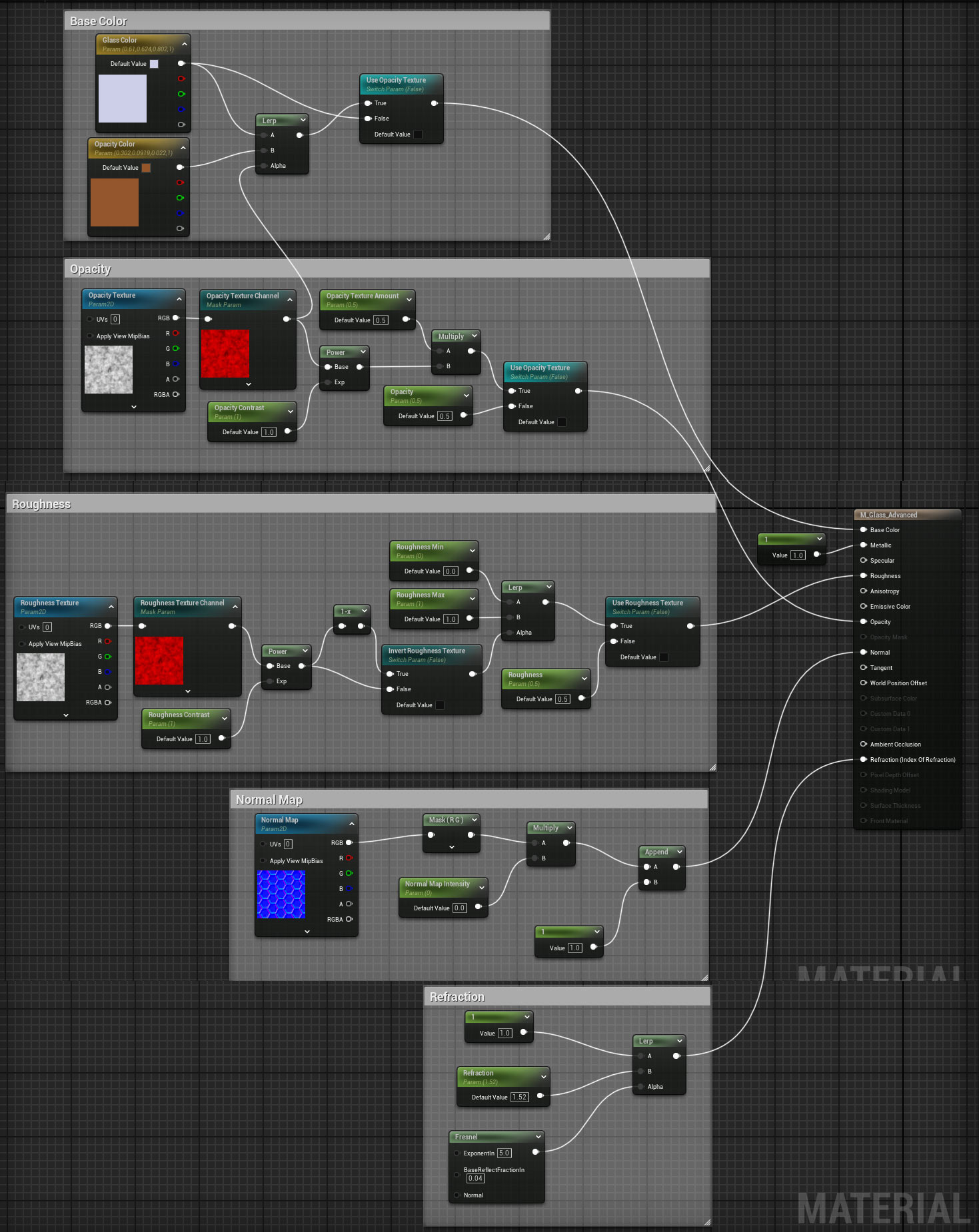
click on image to view full size
Conclusion
You've now created a highly customizable glass material in UE5 with advanced controls for opacity, roughness, normal maps, and base color.
This material allows you to switch between simple and complex setups, introduce texture-based variation and fine-tune the glass's appearance to suit any environment.
UE5 Master Material Creation Tutorial Course
For a deeper dive into creating master materials for environments and props, get "UE5 Master Material Creation" tutorial course. This course covers everything you need to know to craft professional-grade materials in Unreal Engine 5.

SUBSCRIBE & GET FREE UE5 PDF GUIDE
Subscribe to receive NEW/UPDATED and FREE "UE5 Beginner's Quick Start Guide" PDF (90 pages).

Visit this page for more info about the guide...
TOP 7 TUTORIAL COURSES FOR 2026
 Modular Environment Design Masterclass Tutorial Course
 Maya Foundation: Home-Study Course - Model and UV Environments
 Substance 3D Painter Essentials - Master Texturing
 UE5: Fundamentals Vol.1 - Create with Unreal Engine 5
 UE5: Retro Office Project - Create Beautiful Interior Env
 UE5: Master Material Creation - Create Master Materials in UE5
 Preproduction Blueprint: Plan Environments and Level Designs
TUTORIAL CATEGORIES
UE5 FUNDAMENTALS VOL.1 COURSE

UE5: RETRO OFFICE PROJECT

MODULAR ENVIRONMENTS MASTERCLASS

LEARN THE PREPRODUCTION PROCESS

ABOUT WoLD & ALEXG

My name is AlexG. I am self-taught level designer, game environment artist and the creator of World of Level Design.com. I've learned everything I know from personal experimentation and decades of being around various online communities of fellow environment artist and level designers. On World of Level Design you will find tutorials to make you become the best level designer and game environment artist.
Home Terms of Use/Trademarks/Disclaimers Privacy Policy Donate About Contact
All content on this website is copyrighted ©2008-2024 World of Level Design LLC. All rights reserved.
Duplication and distribution is illegal and strictly prohibited.
World of Level Design LLC is an independent company. World of Level Design website, its tutorials and products are not endorsed, sponsored or approved by any mentioned companies on this website in any way. All content is based on my own personal experimentation, experience and opinion. World of Level Design™ and 11 Day Level Design™ are trademarks of AlexG.
Template powered by w3.css